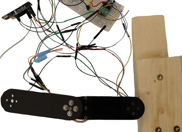
Two-link arm
Group of 3: Semester Project
Background
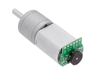
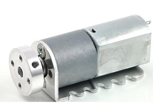
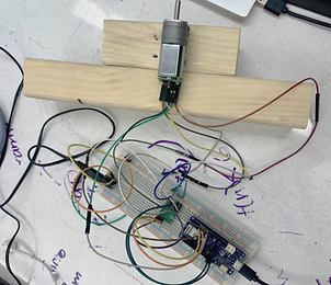
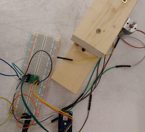
For Electromechanical Systems & Robotics II, the class was divided into groups of 3 and given two DC gearmotors, along with some breadboard components, and two magnetic encoders (shown below).
Each member did the calculations needed for each part on their own and after we had agreed on responses, we would begin adding onto the circuit board together. Each part required additional code that we would begin brainstorming as a team, try out individually, and then come together to complete using the computer that had access to Simulink. Each member had the same kind and quantity of contribution to the project.
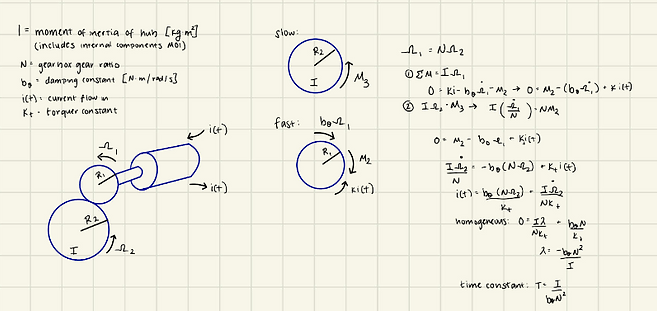
Part I: Initial Derivation (Simplified Equations of Motion)
Task:
-
Derive Equations of motion for the DC gearmotor
-
Use linear system elements to find characteristic equations
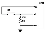
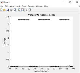
Part II: Analog input with switch and pulldown resistor
Task:
-
Get analog input to work with a switch and pulldown resistor
-
Model the circuit shown above and measure position with the quadrature encoder
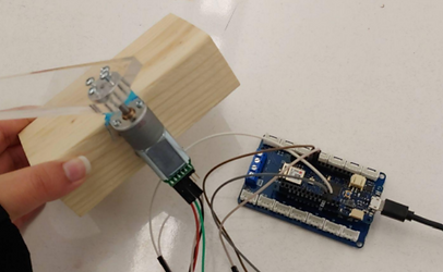
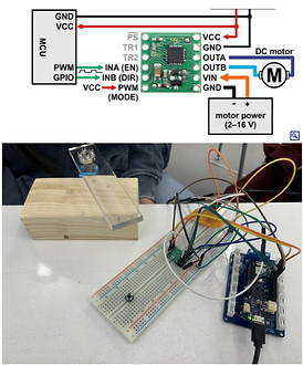
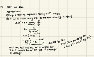
Part III: DC motor open loop response
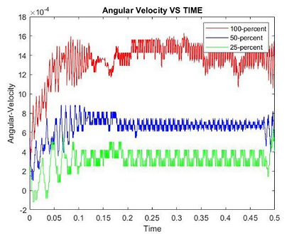
When adding the arm to the motor, the magnitude of the velocities at 100%, 50%, and 25% of the total voltage was smaller than expected, which resulted in a smaller K value. Additionally, the noise made it difficult to get a closer approximation to the K and time-constant values. In the future, it would be beneficial to filter out the collected data perhaps with LabVIEW.
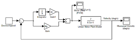
Part IV: Motor speed control (closed loop PI controller)
Task:
-
Build a PI controller to control the motor speed
-
Follow a ramp up and a constant hold at a fixed speed
-
Tune control gains to get a response that follows the setpoint well while not overshooting or causing instability
-
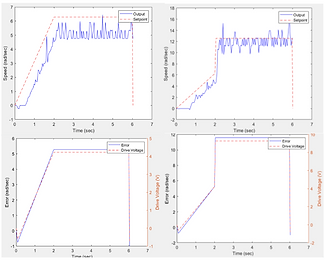
LHS (top and bottom): Speed vs time and Error vs time using a kp value of 0.8 and a ki value of 0
RHS (top and bottom): Speed vs time and Error v time using a kp of 0.8 and a ki of 0.8
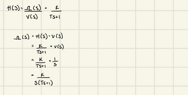
Part V: Motor position control (PD control)
Task:
-
Determine the T.F. for angular position out (individual calculations shown in (a) )
-
Closed loop T.F. using negative feedback off of a position sensor (individual calculations shown in (b) )


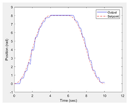
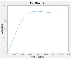
Left: The graph shows the step response of the T.F. with the calculated control values (calculations on the previous slide. The Step Response graph shows an estimated overshoot near 1.04. The steady-state error to step setpoint is ~0 and the 5% setting time was 0.021
Middle: The position of motor vs time is shown in by the blue solid line and the setpoint vs time is shown in red
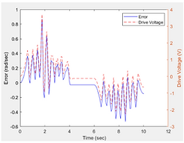
Right: The graph plots error vs time by the blue solid line and the setpoint vs time in red
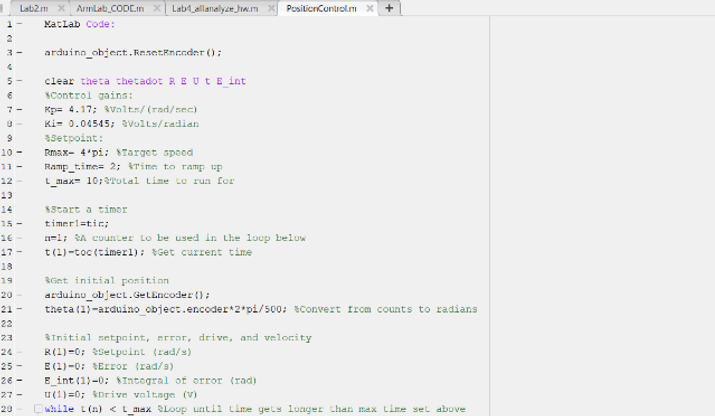
The snapshot of the code above was a few lines of what my team and I worked on. After having each completed the calculations, we talked through what we wanted the code to do and began translating it into code together. Like most of the code written for this project, the three of us would work on a whiteboard and write out an outline and begin taking turns typing the code out.
Part VI: Forward and Inverse Kinematics and Dual Motor Position Control
Forward Kinematics Task:
-
Compute the endpoint of the manipulator as a function of motor angles
-
Calculate the regions that are accessible for the two-line arm
Inverse Kinematics (for a point) Tasks:
-
Calculate the motor angles that are necessary for the desired move
Inverse Kinematics (for a trajectory) Tasks:
-
Calculate a series of motor angles that will move the end of the robot to draw a rectangle

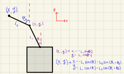
Left: Based on the figure above and the calculations based on θ the robot is able to reach 6 inches in the positive Y-direction, 3 inches in the negative Y-direction, and 6 inches in the positive and negative X-directions.
Middle: This figure shows the position of the robot arms that allow for the “pose” of (X, Y) - (1 inch, 1 inch)
Right: This figure shows a rectangle that begins at (0,6) inches