Electromagnetic Braking System
Group of 6: Semester Project
Background
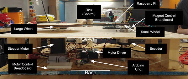
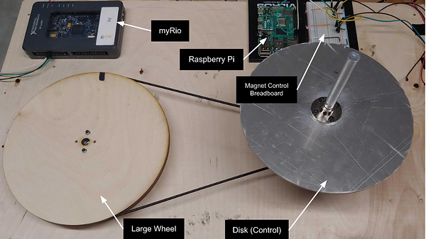
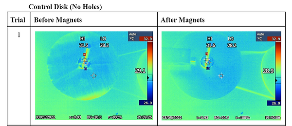
Eddy-current braking systems, commonly used in electric trains, provide a smoother and quieter deceleration. For this project, the effects of eddy currents on the temperature and deceleration of three aluminium disks were tested. Permanent magnets were used to create a magnetic field and an assembly of a Raspberry Pi, Arduino, NI myRIO, 24V motor, motor driver and an encoder were added to a testbed. Each of the three disks (all of the same inertia but different diameter) were run five times and were introduced to magnets after they had reached stable speed. Results indicated little disk temperature change occurred and that increasing the diameter of the disk holes, while keeping inertia consistent, reducing the braking efficiency of the system.
Task Distribution
Our team met bi-weekly for the length of the project, with increased meeting times and length towards the end of the semester. After meeting with our professor to confirm the experiment idea, we each began doing our own research on existing papers regarding electromagnetic breaking systems. We would create an itemized list of what needed to be completed and we all jumped into whatever goals needed to be accomplished. I calculated the appropriate diameters of the aluminum disks and the holes on those disks and the speed ratio. During the wiring and building, each member would begin working on what was needed most, sometimes having to change tasks. I worked the most on the physical building/wiring and the least on MATLAB coding.
Research
One of the goals of the experiment was to essentially test what disk design was the most efficient for braking and whether or not that efficiency was worth the increased heat exchange. A few theories were posed before the ideation phase. These were the following laws:
- Faraday's law of induction: the changing magnetic flux of the electromagnets creates an electric field and current onto the non-ferrous disk
-
Lenz's Law: the induced eddy current will generate a magnetic field on the non-ferrous disk
Design and Prototype
We began by researching the different electronics we would need and bought them, influenced by the shipping time and cost. The original magnets used had too low of a current and saw no change in the speed of the disk after their introduction. After tinkering with said magnets, purchasing new ones, and watching dozens of YouTube videos on coding and wiring, we were ready to build the first prototype.
-
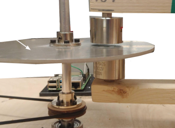
24V motor would cause the rotation of a larger wooden wheel which would then move the aluminium disk at a calculated speed.
-
The encoder attached to the aluminium disk would be attached to an Arduino and myRIO to collect live data
-
LabVIEW would filter out data before the steady speed was reached until a minute after the magnets were introduced
-
Iterations took place, placing a larger focus on the current of the system
Test and Collect
The three disks were tested 5 times each, for about the same length of time. The collected data was filtered out using LabView.
To read my group's report submission, which includes the finalized data, check it out here!
Future changes
-
LabVIEW: The experiment required the collection of data that then needed to be filtered out. Although LabVIEW has given me many headaches, it was the best option. There was a laboratory experiment I had finished during class that involved the same general idea of enclosed for-loops, conditional statements, and arrays that could be tweaked for this project. My confidence in using LabVIEW was not very high, but after many meetings with Learning Assistants and the professor, our LabVIEW code had finally given us the desired data.
-
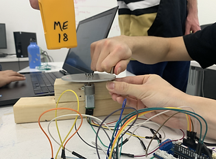
Motor encoder: The original encoder chosen for the project was not shipped and the search for a new encoder that would arrive ASAP began once more. I had experiences with small encoders that are typically used with DC motors. For a 24V motor, the required encoder was much more complicated. The documentation for wiring was difficult to understand, as was the coding. Before it was incorporated into the assembly, we tested it with the motor and a wooden wheel.